Micro structure is obtained when a material undergoes phase transformation which could be mainly due to diffusion or diffusion less process. Diffusion process is progressed by nucleus and growth mechanism such as allotropic transformation; peritectic, eutectoid and eutectic transformation in steel, solidification, recrystallization and grain growth. Martensitic transformation is known as metastable or diffusion less process.
The common example of phase transformation in steel is austenite to change martensite under rapid quenching known as hardening ; austenite to ferrite and pearlite in air cooling known as normalizing, cooling in furnace known as annealing or spheroidizing annealing and tempering of martensite. Microstructure can also be developed or altered by deformation at high temperature accompanied by phase transformation during rolling, forging, extrusion, welding etc. Microstructure can also be formulated by mixing two or more phases in composite. |
| |
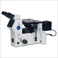
Microstructure is observed when a sample is polished and etched to reveal phases. Microstructure examination is usually performed at magnification from 50 to 1000 in optical microscope. The selection of magnification is based on the size of the phase to be observed. Assuming the resolution of an human eye is 0.1mm, the magnification requires to reveal 1micron (0.001mm) size of phase must be 100times (0.1/0.001). Considering the aberration in the optical lenses such as chromatic, spherical and astigmatism, the appropriate magnification normally maintained for revealing 1micron phase would be 400times.
Similarly the resolution of a microscope can be improved by using green light (500nm wave length ) as illuminating source and an appropriate numerical aperture (NA) in the objective lens by the following equation : |
| |
Resolution of microscope dmin = λ/n  |
Where λ = wave length of light source ; for green light, λ = 500nm
N = refractive index in air n = 1
Sin α = numerical aperture in objective lens |
| |
| Mechanical Test |
Test Method |
Metallographic sample preparation
Grain size
Banding/Orientation of microstructure
Graphite flakes
Inclusion rating
Decarburization depth
Case depth
Marco/Micro etch
Ferrite by metallography
Ferrite by replica metallography
Grain size in QT steel
Macroscopic examination- Fillet/Groove weld
Pull out test on mock up
Leak path test
Pull out test for tor steel bar
Macroscopic examination of weld
Volume fraction
Ferrite measurement
Classification of duplex steel |
ASTM E3
ASTM El 12
ASTM E1268
IS 7754
ASTM E45 (Method A), IS 4163
IS 6396
IS 6416
ASTM E340, E381, E407
DMS-Met-1
ASTM E1351
ASTM El 12/ DMS-Met -2
ASMESexlX
ASME / ASTM
ASME/ ASTM
IS 1786
ASME Section IX
ASTM E 562
ISO 8296
ASTM A923 |
|
| |
 |
| |
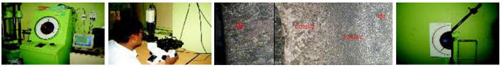
Measurement of grain size : Normally all materials are polycrystalline and it consists of aggregate of many crystals and each crystals are called a grain and each grain is separated by a distinctive boundary which is called grain boundary. The casting has very large grain that can be resolved with naked eye or low power microscope and it is designated as macroscopic examination. The features of small grains cannot be examined at low magnification and it requires magnification of at least 100times.
In heat treated steel, the measurement of prior austenite grains is very complicated and difficult. In martensite or tempered martensite, the prior austenite grain cannot be revealed and usually martensite forms within the austenite grains. The prior austenite grain is the size of austenite grains that are formed during soaking in the heat treatment process such as austenitizing. The size of the prior austenite grains is directly related to the properties of heat treated steel. The prior austenite grain can be revealed by etching process as per ASTM E 112.
Following normalizing and annealing heat treatment , we measure the ferritic grain size in ferrite and pearlite. The prior austenite grain size can also be measured in forged and normalized heat treatment. In certain grade of stainless steel type 300 series, we measure austenite grains. |
| |
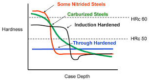
Case depth : Case depth is the thickness of a hardened layer on a specimen; normally gear, cam, spline and many other rotating transmission output parts are case hardened. Case hardening improves the resistance to abrasion and fatigue under dynamic loading. There are three well established heat treatment procedures to impart hardness at the surface of material. These methods are known as case carburizing, case nitriding and induction hardening.
The case carburizing is a heat treatment process accompanied by change in chemical composition at surface and is performed at temperature above AC3 temperature for sufficient time in a carbon rich environment in order to enrich surface with high carbon. Since carbon has high solubility in austenite ( > 9000C ), carburizing heat treatment process produces high carbon in the range of 0.8% to 1% at the surface while maintaining a base carbon of 0.2% at core. If carbon exceeds 1%, the case carburizing layer contains inter granular carbide and high proportion of retained austenite. The case carburized is characterized by surface hardness, effective case depth, total case depth and core hardness as per DIN EN ISO 2639 and IS 6416 by microscopic and hardness method. The common case carburized steels are AISI 8620, DIN 20MnCr5, 16MnCr5, |
| |
 |
| |
| Nitriding is defined as thermo chemical diffusion process of a work piece in order to enrich the surface layer with nitrogen. Case nitriding is performed at temperature between 3500C and 5900C. Since nitrogen has limited solubility in ferrite, a nitrided layer which is commonly known as white layer (Fe2N ) forms on the surface. This layer is connected to the diffusion zone that contains precipitated iron nitride
evenly distributed in the steel (ferrite) resulting high hardness of at least 600HV. The case nitriding is characterized by surface hardness, effective case depth, total case depth and core hardness as per DIN 50190-3 by hardness measurement and IS 6416 by microscopic and hardness method. The common case nitriding steel is EN41B containing 1% aluminum. |
| |
 |
| |
| Induction hardening is a case hardening heat treatment process in which steel is a heated by induction heating to a temperature above the transformation temperature followed by rapid quenching . The quenched metal undergoes a martensitic transformation resulting high hardness at the surface while the core remains unaffected. The induction hardening is determined by surface hardness, effective case depth, total case depth and core hardness as per DIN 50190-2 by hardness measurement and IS 6416 by microscopic and hardness method. Carbon and alloy steel with carbon content of 0.40-0.45% are most suitable for induction hardening. |
| |
| In metallographic method sample is sectioned, or removed, mounted , polished and etched then to reveal the depth of case. Normally an etched sample is examined at 100 magnfication. In hardness method, a cross section of case hardened sample with hardened surface layer is sectioned, mounted and the hardness is measured starting vertically from surface at regular interval from the surface. the hardness values thus obtained are recorded as function of distance from the surface. |
| |
| DMS has been following specified specification and customer requirement for determining the case depth employing national and international standard which are given below : |
| IS 6416 specification |
Carburized |
Nitrided |
Induction hardened |
| Load |
HV 0.1(0.98N)<Load<10kgf(98.0N) |
HV 0.1<Load<10kgf |
HV 0.1<Load<10kgf |
| Total case depth |
Hardness or microscopic |
Hardness or microscopic |
Hardness or microscopic |
| Effective case depth |
Hardness at specified depth , test interval 0.1mm |
Hardness at specified depth test interval 0.1mm |
Hardness at specified depth, test interval 0.1mm |
| Surface & core |
Hardness |
Hardness |
Hardness |
|
| |
| Parameter |
Carburized |
Nitrided |
Induction hardened |
| Specification |
EN ISO 2639 |
DIN 50190-3 |
DIN 50190-2 |
| Load |
HV 0.1<Load<10kgf; HV1 |
HV 0.1<Load<10kgf, HV0.5 |
HV 0.1<Load<10kgf, HV1 |
| Total case depth |
Hardness ; 3xCHD |
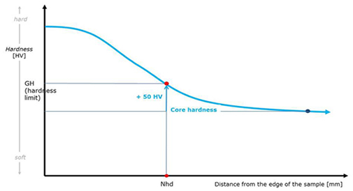
Hardness ; Core hardness +50HV or 3xNHD |
Hardness ; Core hardness +100HV; 3xGH |
| Effective case depth |
Hardness; depth at 550HV1 |
Hardness; at specified depth |
Hardness; Hardness; at specified depth |
| Effective case depth by formula |
CHD,mm = d1+[ {(d2-d1)x (H1-HS)}/ (H1-H2)], mm |
NHD = several reading |
Rht, mm = t1+[ {(t2-t1)x (H1-GH)}/ (H1-H2)], mm |
| Test interval |
0.1 or max 0.3mm |
0.1mm |
0.1 or max 0.3mm |
| Core hardness |
>450HV1 or 3xCHD depth |
3XNHD depth |
3XGH depth |
|
| |
| CHD _ threshold hardness in carburized case, NHD _ threshold hardness in nitriding case, GH _ threshold hardness for induction hardened case |
| |
Retained austenite measurement : The transformation of austenite to martensite is generally achieved by hardening process. Martensite transformation begins at temperature MS and completes at temperature MF and both these transformation temperatures depend on mainly carbon and alloy element in steel. MS and MF temperature of steel can be obtained from a TTT (Time Temperature Transformation) diagram. There are many equations available to describe the transformation of austenite into martensite during cooling and few formula’s are given below :
MS 0C = 539-(423x%C)- (30.4xMn%)- (12.1xCr%)- (17.7 x Ni%) – (7.5xMo%) and for high alloy steel considering the effect of grain size ; MS 0C = 550-(350x%C)- (40xMn%)- (20xCr%)- (17 x Ni%) – (10Mo%)- (8XW%)-(35 XV%)-(10xCu%) +(15xCo%) + (30xAl%)
With increase of carbon content as in a case of carburizing process, both MS and MF are depressed which results in incomplete transformation of austenite to martensite and producing retained austenite. Retained austenite is very common in steel containing above 0.8 % C or high alloy steel. Retained austenite can have a detrimental effect on mechanical properties, fatigue strength, toughness, hardness etc. |
| |
 |
| |
| Retained austenite can be measured by metallographic method as per ASTM E 562 and also by X ray diffraction method ASTM E895. At DMS, we determine the retained austenite by manual counting method following ASTM E 562. However this is useful when the volume fraction of retained austenite is more than 5% because optical microscopic method could not detect retained austenite below 5%. |
| |
| Inclusion : Inclusions are non metallic compound formed during melting, pouring and also refining process. Inclusions are mainly two types ; exogenous and endogenous. Exogenous inclusions are formed due to slag, refractory, casting mould while endogenous inclusions are sulphide, silicate oxide etc. Carbides and nitrides are generally not considered as inclusion. There are many microscopic methods that have been developed to determine the inclusion content in steel. These methods cover the measurement inclusion as inclusion rating as per ASTM E 45, IS 4163 etc. Inclusions in steel have been described by their shapes and chemical composition. Type A inclusion is known as MnS suplhide inclusion which are generally observed as elongated stringer. The fragmented , broken and cluster of oxide which is made aluminum is categorized as Type B. The elongated, thin and shiny inclusion is known as Silicate Type C and globular oxide made of iron is known as Type D. |
| |
| Decarburization : Decarburization is a loss of carbon from the surface of the products made of steel. It occurs during hot working or heat treatment in an uncontrolled environment or environment rich in oxygen. Decarburization may be complete or partial. The complete decarburization layer is defined as region where only ferrite is present. Partial decarburization is the region consisting of mixed phases other than the ferrite. The complete decarburization is easily detectable for all steel but for high carbon steel or alloy steel, partial decarburization is difficult. Decarburization reduces the hardness at surface, strength and fatigue properties of steel. There are many microscopic methods that have been developed to determine the decarburization in steel. However at DMS we determined decarburization depth and type of decarburization by IS 6396 and ASTM E192. |
| |
 |